Basic Raspberry Pi Case – Tutorial
In this tutorial, we will show you how to make a basic case for the Raspberry Pi 4 Model B in Fusion
360.
This isn’t intended to be a final version of the case but to get you comfortable with the methods
involved. You can then take these methods to customise the case further. For example the sketch
and extrude functions could be used to add embossed logos, ventilation grills or printed feet etc.
To get started with this tutorial you will need to download a CAD model of the Raspberry Pi 4 model
B. We used the version here. There are ways to start from Fusion 360’s inbuilt PCB import and
design system, but that is complex and would deserve its own tutorial.
You will want to upload the .SLDASM and all the .SLDPRT files into Fusion. .SLDASM is the solidworks
assembly file and Fusion 360 will read it to understand how all the .SLDPRT part files go together. If it
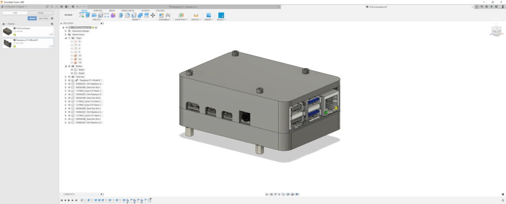
worked then you will see something similar to the below image.

You don’t want to mess around with this file so it’s best to make a new file to start your case design in. Once you have your new case file you can import the Raspberry Pi design into it. This way you won’t be able to mess around with the Pi model, but you will be able to use it as a reference for the rest of the design.

The next step is to make the drawing that will be the basis for the rest of the design. Select the XZ plane and right-click to create a sketch.
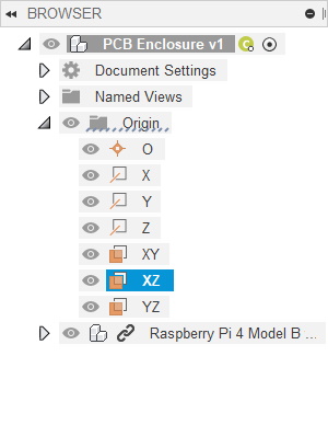
On this model the XZ sketch plane is parallel with the Pi PCB and running through the middle.
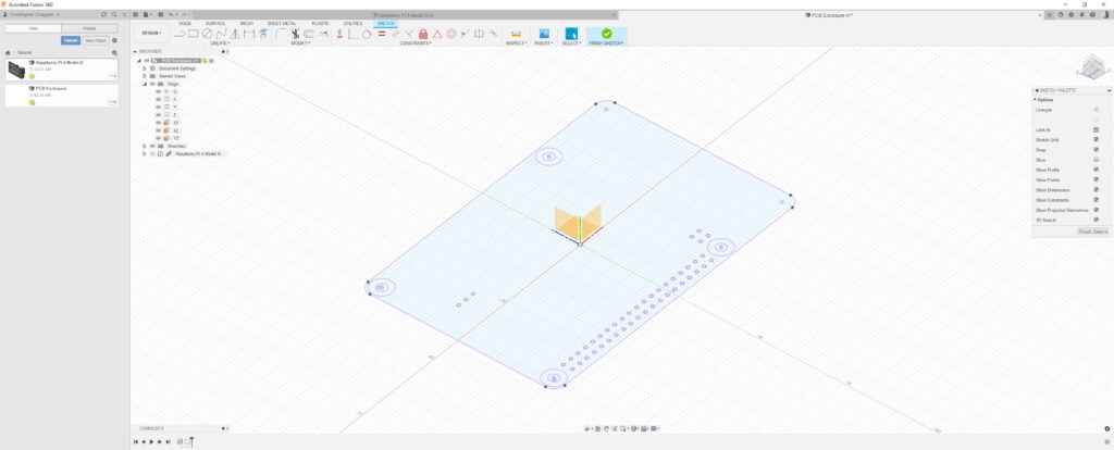
You want to use the project tool to project the shape of the Pi onto the sketch plane. Ensure the PCB and the gold rings are selected.

To see what you’re doing you will now hide the Pi by clicking the small eye image next to the ‘Raspberry Pi 4 Model B’ entry in the browser.
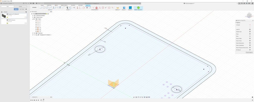
You now want to add the lines which will be the inner and outer walls. To do this you use the offset tool in the ‘modify’ part of the sketch interface.
You can only offset from drawn or projected geometry. You can not offset from other offset geometry. Which is a bit annoying in this case as to make a 2mm wall we need to offset by 1mm and then offset by 3mm.
Additionally add a 5mm circle centred on the Pi screw holes. These will be the pillars the Pi sits on.
Now extrude these parts out. Notice how the extrusion is set to start at the object and not on the sketch plane. This means it starts where the Pi PCB ends and not in the middle.
I selected 10mm, but this might be something you will want to change.
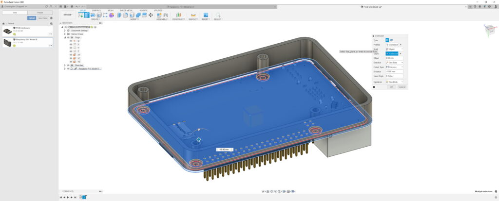
Now you can select the new face and create a new sketch. Use project to project the objects you just extruded. You can then extrude this. Ensure the holes for the screws are not selected, otherwise there would be no way for the screws to come out.
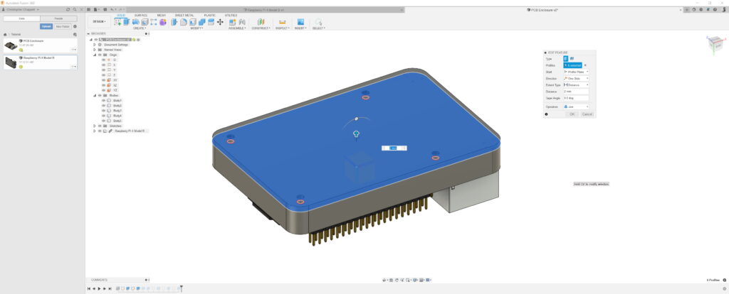
Flip the view over so you are looking at the other side. Select the top of the wall and select extrude. This will automatically try to extend the wall, but you want to select ‘new body’ in the operation tab. This makes the new wall a separate piece.
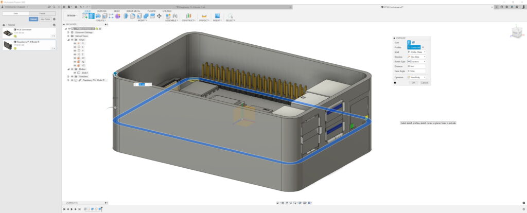
The next step is to do the pillars. This time though you select the 5mm rings in the first sketch. Observe how once again the start point is from the PCB and not the sketch. This means there will be a sketch between the pillars to fit the PCB.
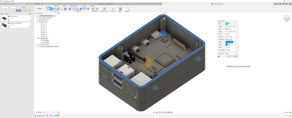
Repeat the step used to make the base but on the top.
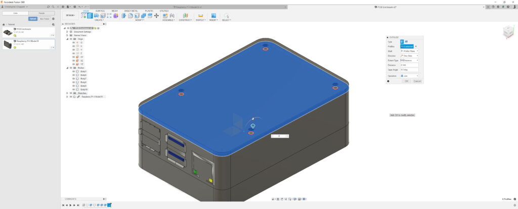
As you might notice the plugs are sticking through the wall. This would be an issue if you want to close the case or plug the Pi sockets into anything.
To make holes for the sockets you need to create sketches on the walls that you want the holes to be in.
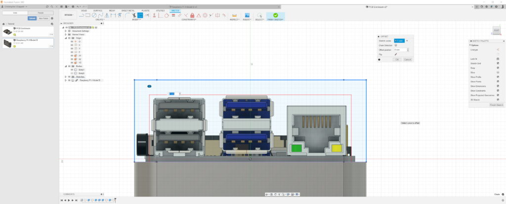
Here using project and offset are convenient. You can also use other sketch tools to make the holes a tighter fit.
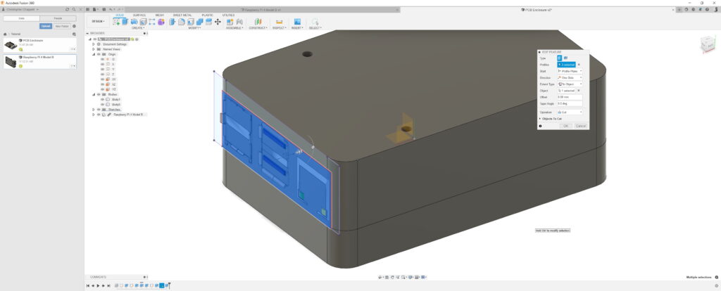
In this extrude I selected the Extent type to Object. I then selected a corner, which is now shown with a light blue point. As part of the case is curved, a simple extrude by X mm’s might not have gone all the way through the wall. Selecting this point means that it has gone through the entirety of the curve.
Create a sketch on the other wall where connectors are located.
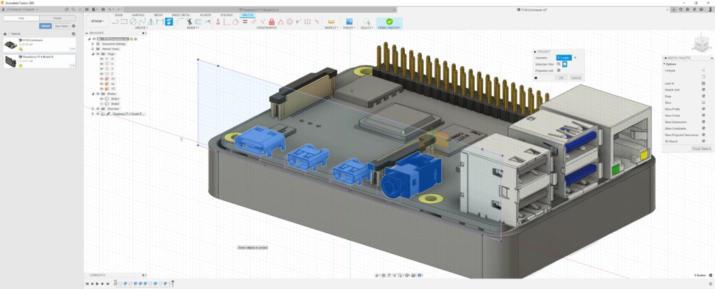
Project the connector pieces so you have something in the sketch to offset from.
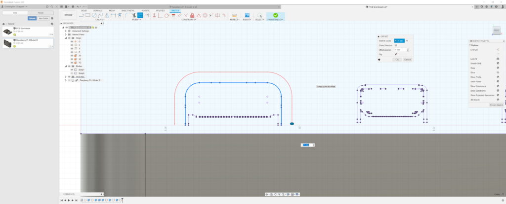
Use the line tool to extend the offsets to the edge of the case.
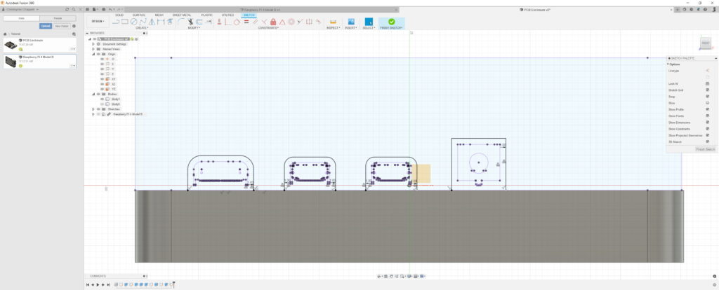
Extrude the profiles to cut out the holes.
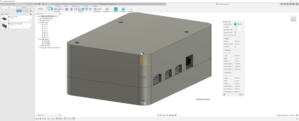
Measure the length of the screw hole. In this case the length is 34mm and has a diameter of 2.7mm.
In this case we want a screw 2.5mm and about 40mm long. The extra length gives space for a nut to seal the case. You can find these parts in the McMaster-Carr database along with 3d models (click the blue number and select the .step option).
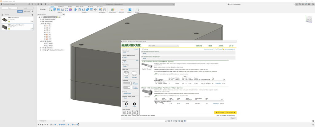
Also added Nylon spacers to act as feet. You can use the move, copy and snap point to point options to position the screws and nuts in the correct locations.